Meshing a Polycrystal Image Obtained by Synchrotron X-Ray Diffraction
Introduction
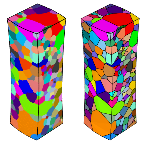
Methods such as diffraction contrast tomography (DCT) provide 3D polycrystal maps that are usually defined as (i) a field of grain identifiers (or “ids”) and (ii) grain orientations. Neper can read in such maps and process them in different ways. In particular, it can generate the optimal tessellation (made of convex cells) that corresponds to the polycrystal and mesh it for FEM simulations [CMAME2018].
An AlLi polycrystal scanned by DCT at the Materials Science beamline of ESRF (ID11) is used as an example. The polycrystal contains 299 grains and is described by a 16-bit binary .dat data file that correspond to a 3D raster of 214 x 214 x 462 voxels of size 3.5 \(\mu\text{m}\), on which grain ids are defined. Grain ids are strictly positive, while 0 represents empty voxels. The orientations corresponding to the grains are defined as Rodrigues vectors in a separate, ASCII file. The data were obtained in the context of the 3DPLASTICITY French ANR project.
Generating a Clean Raster Tessellation (.tesr)
Converting the Raw Files (.dat, Orientations) into a Neper .tesr File
Neper uses a (standalone) .tesr (raster tessellation) file to describe a DCT-type polycrystal, which embeeds not only the information contained in the .dat file and the grain orientations, but also the numbers of voxels, the voxel size, the crystal type, etc. The raw .dat file can be read by Neper using a minimal tesr file, named e.g. AlLi-load.tesr, with the following content:
***tesr
 **format
   2.1
 **general
   3
   214 214 462
   3.5e-6 3.5e-6 3.5e-6
 **data
   binary16
  *file AlLi.dat
***end
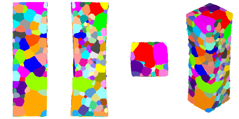
It is possible to visualize the polycrystal as follows:
$ neper -V AlLi-load.tesr -print AlLi
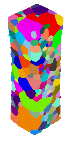
where the grains are colored by their ids.
The grain orientations (and the crystal symmetry) can be added to the file through a **cell section:
***tesr
 **format
   2.1
 **general
   3
   214 214 462
   3.5e-6 3.5e-6 3.5e-6
 **cell
   <number_of_cells>
  *crysym
   <crysym>
  *ori
   <descriptor>
   <orientations>
 **data
   binary16
  *file AlLi.dat
***end
where <number_of_cells> is the number of cells, <crysym> is the crystal symmetry is the orientation descriptor (e.g., rodrigues:active) and <orientations> is the list of orientations (the crystal symmetry could also have been defined a posteriori, using the -oricrysym option). If the grains are not numbered contiguously from 1, their ids must be provided in the **cell/*id section in order to be able to provide an *ori section.
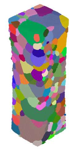
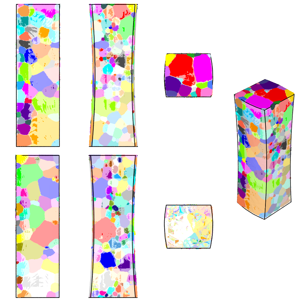
It is now possible to visualize the polycrystal colored by its grain orientations:
$ neper -V AlLi-load.tesr -datacellcol ori -print AlLi-ori
The tesr file can be made a standalone file (not reading from AlLi.dat any more), as follows:
$ neper -T -loadtesr AlLi-load.tesr -o AlLi
The new file is written using Neper’s default behavior. Optionally, the data encoding format can be specified using -tesrformat. (The tesr can be written back to a raw data format anytime using -tesrformat raw.)
The resulting tesr describes all of the data obtained by DCT, and later operations to the file will be applied using Neper -T options. The procedure is to load it using -loadtesr and apply transformations using -transform. Several transformations can be applied successively, on a single run, by combining them with ,. It is generally a good idea to write the resulting tesr to a different file, using -o.
Note
To reproduce exactly the images below, add the following line to your $HOME/.neperrc file (or to a local configuration file to be loaded with --rcfile):
neper -V -imagesize 250:500 -cameracoo x+5:y+5:z+5 -cameraangle 6
Cleaning the Tesr: Raster Trimming and Cell Renumbering
At this point, the polycrystal is generally surrounded by a relatively large empty volume, which makes the tesr file larger than necessary. Also, the cells may not by numbered contiguously from 1 (in the **cell/*data section). This can be fixed as follows:
$ neper -T -loadtesr AlLi.tesr -transform autocrop,resetorigin,renumber,resetcellid -o AlLi-c
autocrop generates a **general/*origin section so that the voxel coordinates are retained, and it is here reset to (0, 0, 0) using resetorigin. renumber generates a **cell/*id section so that cell identifiers are retained, and they are here reset to a contiguous sequence starting from 1 using resetcellid.
Aligning the Polycrystal
The polycrystal axes may not perfectly coincide with the tesr axes. It is generally a good idea to fix this, at it will later facilitate the domain definition. This can be analysed via orthographic views along the 3 coordinate axes:
$ neper -V AlLi-c.tesr -print AlLi-c            \
          -cameraprojection orthographic        \
          -cameracoo x+8:y:z -print AlLi-c-x    \
          -cameracoo x:y+8:z -print AlLi-c-y    \
          -cameracoo x:y:z+8 -print AlLi-c-z
It is possible to determine by elementary image processing that the polycrystal is tilted by -0.6° around the x axis, 1° around the y axis, and 2° around the z axis. This can be corrected simply by applying the rotations successively, but, before the rotations, a 10-voxel buffer is added around the polycrystal to accommodate the new positions, and, after the rotations, the raster is cropped again. Of course, Neper rotates the whole polycrystal (including the grain orientations). The command is as follows:
$ neper -T -loadtesr AlLi-c.tesr \
           -transform "addbuffer(10,10,10),rotate(1,0,0,0.6),rotate(0,1,0,-1.0),rotate(0,0,1,2),autocrop,resetorigin" \
           -o AlLi-cr
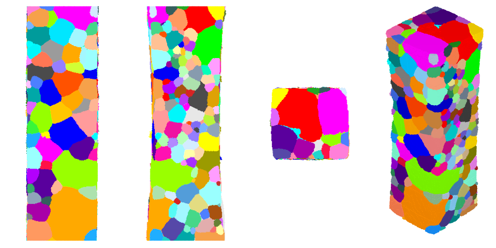
The tessellation can be visualized again after the transformation:
$ neper -V AlLi-cr.tesr -print AlLi-cr-xyz       \
          -cameraprojection orthographic         \
          -cameracoo x+8:y:z -print AlLi-cr-x    \
          -cameracoo x:y+8:z -print AlLi-cr-y    \
          -cameracoo x:y:z+8 -print AlLi-cr-z
In general, but especially as a result of this transformation, the top and bottom surfaces are not flat nor perfectly horizontal, while this is usually desired for simulations. This can be fixed by cropping the tessellation by a few voxels along the z axis, as follows:
$ neper -T -loadtesr AlLi-cr.tesr \
           -transform "crop(cube(-10,10,-10,10,originz+5*voxsizez,originz+(voxnbz-5)*voxsizez)),autocrop,resetorigin,renumber,resetcellid"
           -o AlLi-crc
The tesr can be visualized as before (along x and y, and in perspective):
$ neper -V AlLi-crc.tesr -print AlLi-crc-xyz     \
          -cameraprojection orthographic         \
          -cameracoo x+8:y:z -print AlLi-crc-x   \
          -cameracoo x:y+8:z -print AlLi-crc-y   \
          -cameracoo x:y:z+8 -print AlLi-crc-z
Defining the Domain
The last step is to define the domain, i.e. the actual external envelope of the polycrystal, and to have the polycrystal fill it perfectly. When the polycrystal is not cubic, this is certainly the most tedious step. For this polycrystal, the domain can be represented by a cube slightly slimer than the tesr in the y direction (by 2 x 3 voxels) and of the same size as the tesr in the z direction (which has already been “cropped”), and cut by 2 torus in the x direction. We generate it through a 1000-cell tessellation:
$ neper -T -n 1000 -domain "cube(1,0.479,1.5785):translate(-0.25,0.0105,0)" \
           -transform "cut(torus(1.119,0.231,0.78925,0,0,1,10,8.916),torus(-0.58,0.231,0.78925,0,0,1,10,8.916))" \
           -o domain
The domain can be superimposed onto the tesr as follows. First, we generate an image of the domain at the pov:objects format:
$ neper -V domain.tess                          \
           -showcell 0                          \
           -showedge "domtype==1"               \
           -showface "domtype==2"               \
           -dataedgerad 0.0035                  \
           -datafacetrs 0.5                     \
           -imageformat pov:objects             \
           -print domain
The, we plot the polycrystal as before, but we also include the domain file:
$ neper -V AlLi-crc.tesr                        \
          -includepov domain.pov                \
          -print AlLi-crcd-xyz                  \
          -cameraprojection orthographic        \
          -cameracoo x+8:y:z -print AlLi-crcd-x \
          -cameracoo x:y+8:z -print AlLi-crcd-y \
          -cameracoo x:y:z+8 -print AlLi-crcd-z \
          -cameracoo x-8:y:z -print AlLi-crcd-xm\
          -cameracoo x:y-8:z -print AlLi-crcd-ym\
          -cameracoo x:y:z-8 -print AlLi-crcd-zm
This shows how closely the domain fits the polycrystal.
Adjusting the Tesr to the Domain
The tesr can now be adjusted to the domain. To do so, the grains are grown until they fill the entire tesr and the tesr is then intersected with the domain, and we finish by the usual autocrop,renumber:
$ neper -T -loadtesr AlLi.tesr -transform "grow,tessinter(domain.tess),autocrop,renumber"
The tessellation may contain an *origin at this point, which we can determine as follows:
$ neper -T -loadtesr AlLi-crcf.tesr -stattesr originx,originy,originz
As per the AlLi-crcf.sttesr file, the origin is 0 0.0105 0. We can reset it simply, and apply domain.tess the same transformation (this is only for the visualization that follows):
$ neper -T -loadtesr AlLi-crcf.tesr -transform resetorigin
$ neper -T -loadtesr domain.tess -transform "translate(0,-0.0105,0)"
Finally, the grains can be cleaned from potential “satellites” (voxels that would be disconnected from the rest of the grain):
$ neper -T -loadtesr AlLi-crcf.tesr -transform "rmsat,grow,tessinter(domain.tess)" -o AlLi-crcfs
For this polycrystal, less than 200 voxels are filtered.
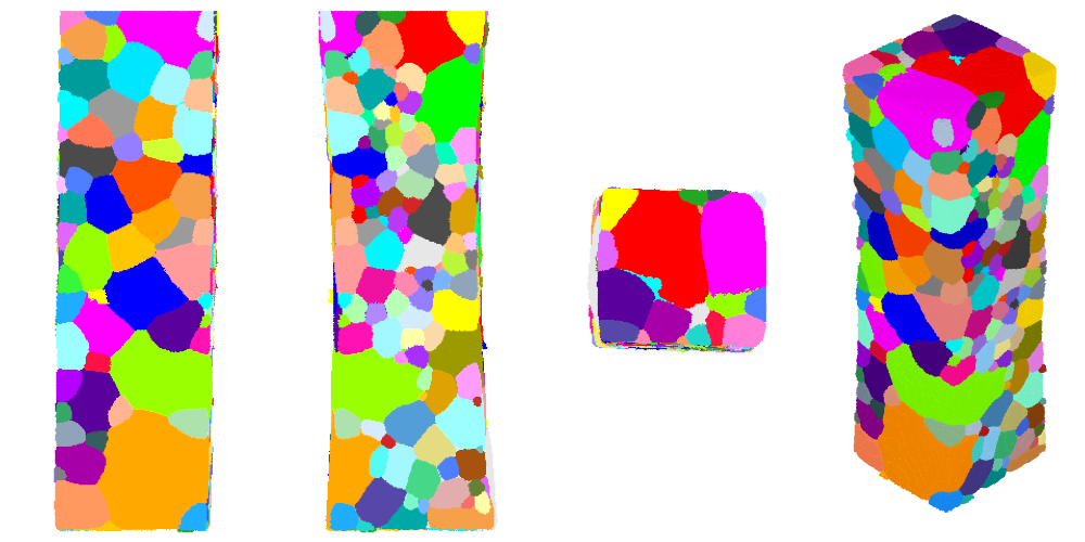
We can visualize the final tesr, this time taking advantage of the definition of the domain to highlight the polycrystal edges:
$ neper -V domain.tess                          \
           -showcell 0                          \
           -showedge "domtype==1"               \
           -dataedgerad 0.0035                  \
           -datafacetrs 0.5                     \
           -imageformat pov:objects             \
           -print domain

$ neper -V AlLi-crcf.tesr                       \
          -includepov domain.pov                \
          -print AlLi-crcfs-xyz                 \
          -cameraprojection orthographic        \
          -cameracoo x+8:y:z -print AlLi-crcfs-x\
          -cameracoo x:y+8:z -print AlLi-crcfs-y\
          -cameracoo x:y:z+8 -print AlLi-crcfs-z
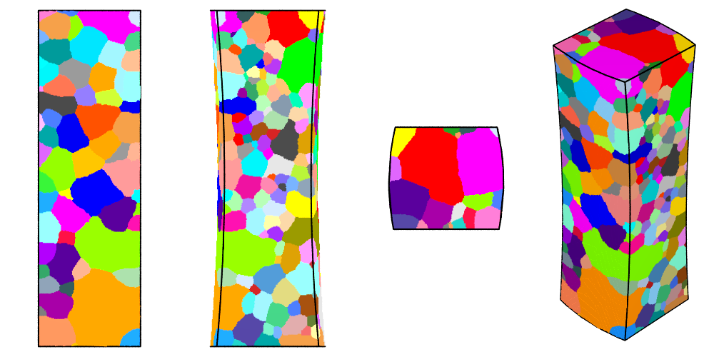
The tesr is now perfectly clean and ready for further processing.
Generating a Tessellation (.tess)
A (scalar) tessellation (.tess) can be generated from the tesr, for meshing. Since the domain has to be convex (and we can cut the tessellation afterwards), we use the bounding box of domain.tess. We make the domain a little larger along x to enable for clean cutting:
$ neper -T -n from_morpho                                            \
           -domain "cube(0.5687,0.4790,1.5785):translate(-0.01,0,0)" \
           -morpho "tesr:file(AlLi-crcfs.tesr)"                      \
           -morphooptiobj "tesr:pts(region=surf,res=10)"             \
           -transform "cut(torus(1.119,0.231,0.78925,0,0,1,10,8.916),torus(-0.58,0.231,0.78925,0,0,1,10,8.916))" \
           -o AlLi
Even if the tesr does not fill the domain, and because of the form of the objective function, the method works just as well as in the standard case. We can visualized the tess:
$ neper -V AlLi.tess -print AlLi-tess
It is also useful to apply regularization, for future meshing; we choose to reduce the small edge length (threshold) to 0.25 times its default value:
$ neper -T -loadtess AlLi.tess -reg 1 -rsel 0.25
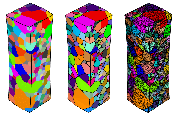
Generating a Mesh (.msh)
A mesh can be simply obtained from the tess; we adapt the progression factor to the value of -rsel used before:
$ neper -M AlLi-r.tess -rcl 0.5 -pl 8
$ neper -V AlLi-r.tess,AlLi-r.msh -showelt1d all -print AlLi-mesh